Introduction to ARM Assembly
A foundational guide to understanding ARM assembly instructions and their role in computer architecture. Learn about OPCODES, CPU architecture, ARM cores, and how high-level code translates to machine instructions.
This article was originally published on Medium.
Computers only understand binary-coded data. This data can contain a wide variety of information. To understand these instructions a computer would need to process it and make ‘sense’ out of it. The CPU of the computer is specifically designed for this task. As we all know, computers to do anything need to be given specific instructions and these instructions are provided to the computer using programming languages. However, there is more to this. Most of the programming languages are high-level languages which is more like English. CPUs don’t understand English, so we process the high-level programming languages and convert them into Assembly language. This is closer to what a computer would understand but far from what it could process. A typical assembly code consists of mnemonics which represent OPCODES operations and operands. This is understood by another program called Assembler.
What are OPCODES?
Opcodes are specific and limited instructions that the CPU of a particular architecture understands and can process and finally execute. Every CPU is designed differently, with different arrangements of registers of different sizes of the registers. Manufacturers like Intel, AMD, MediaTek, etc release a document with their CPUs which contains guidelines on how to program the specific model and generation of CPU. This also includes the set of operations the CPU can perform i.e., OPCODES. This is usually referred to as ISA (Instruction Set Architecture). We shall discuss all these in detail in the CPU architecture section of the course.
CPU Architecture — ARM cores
ARM processors follow RISC (Reduced Instruction Set Computer) architecture. Most instructions execute in a single cycle, orthogonal register set, and load-store architecture. In other words, RISC philosophy tries to reduce the complexity of instruction and only allow simple instructions in the design. This architecture tries to decrease the number of clock cycles needed to complete an instruction and thus increase the frequency of instructions.
To modify any variable in memory, you need to load the value of the memory in the core and then process/modify it and put it back in the memory. The other architectures out there have some ways of directly modifying the values in the memory, whereas ARM is designed differently. Thus, ARM can only perform LOAD and STORE operations in the memory (which makes more sense to the general perception of what memory is designed for).
Most internal registers are 32-bit registers except some registers for processing vectors. They are generally processed by 32-bit ALU and memory is generally manipulated in 32-bit units i.e. the word size for ARM is 32 bits (fixed).
- WORD SIZE = 32 bits
- HALFWORD SIZE = 16bits
- DOUBLEWORD SIZE = 64 bits
ARM ISA has 32 32-bit ARM instruction sets and 16/32-bit Thumb ISA that provides better code density. ARM processors could switch between ARM ISA and Thumb ISA, termed as Interworking. This is automatically handled by the compiler/linker and the programmer need not worry about it.
Operating Modes
Most processors have two different modes of operation, one of which is privileged and the other is not, for example, you might have heard of User mode and Supervisor Mode. Wherein user mode fewer things can be done as compared to running in the privileged mode. This is specifically done to prevent critical unintended fatal operations for safety and security purposes.
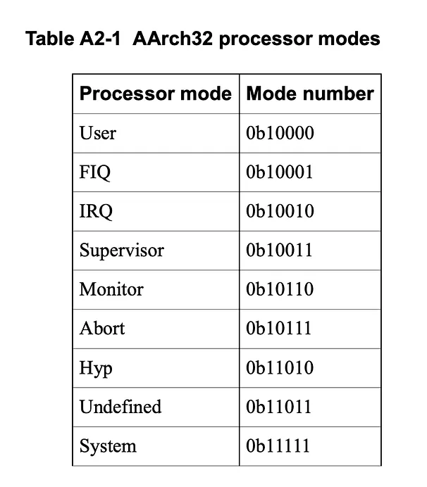
ARM cores have 7 specific operating modes: Each of these has its own stack space and a subset of private registers. This is known as Register banking which makes handling nested exceptions efficient.
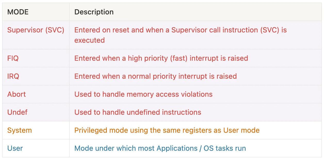
 Source: ARM Instruction Set Reference Guide v1.0
Thus the unprivileged mode is where the OS and user tasks execute. We will focus more on the registers sets for the User mode as we will usually deal with these registers.
User mode registers
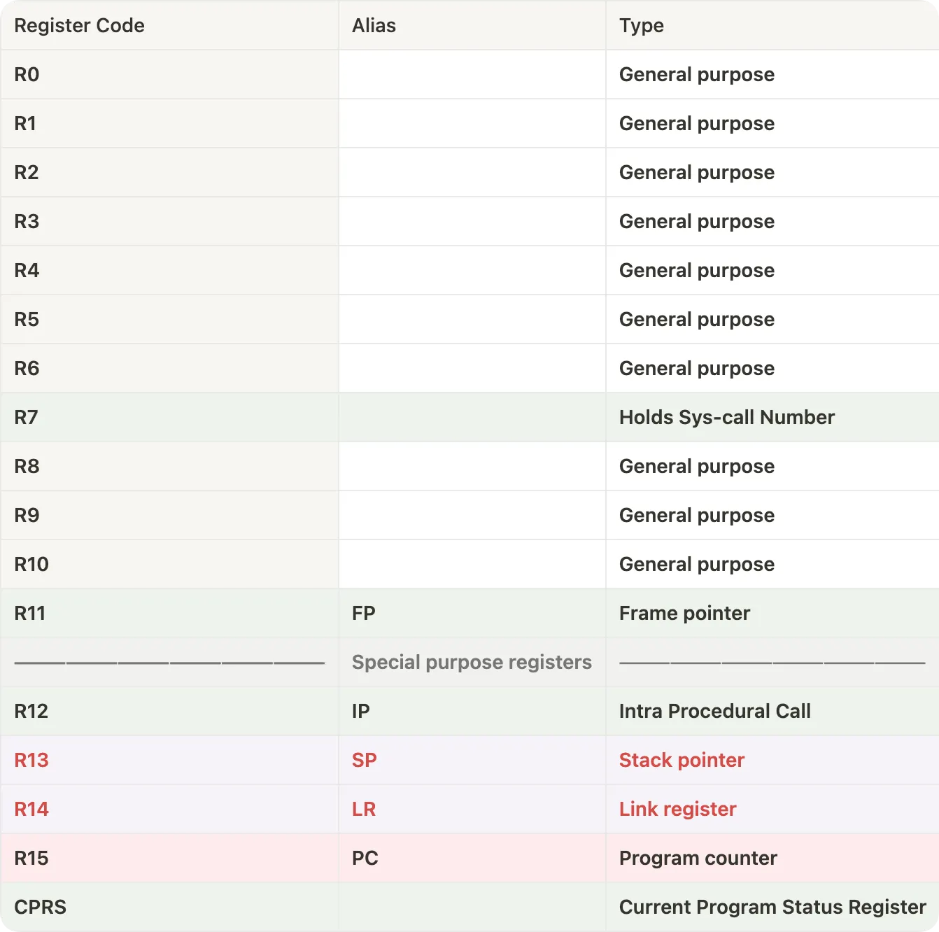
When the operation mode is changed the R13 and R14 i.e. the Stack pointer and the Link Register change because as mentioned before, each mode has its own space in the stack and its subset of private registers.
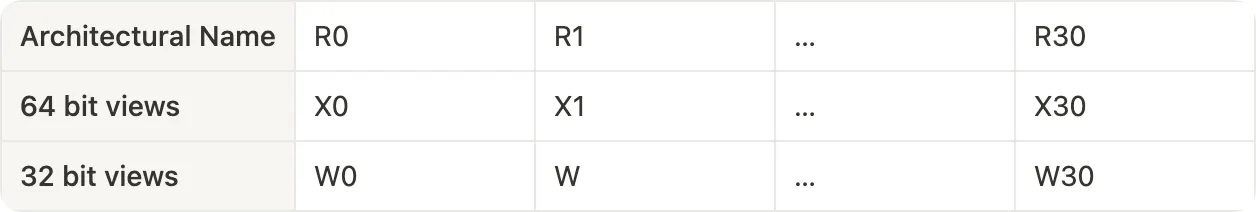
In AAArch64 ISA their registers are referred differently. The architectural names are referred to with the prefix R while in 64-bit ARM processors, it could be referred to as W or X where W refers to size 32 while X refers to 64-bit size. For example, register R0 could be referred to as W0 or X0.
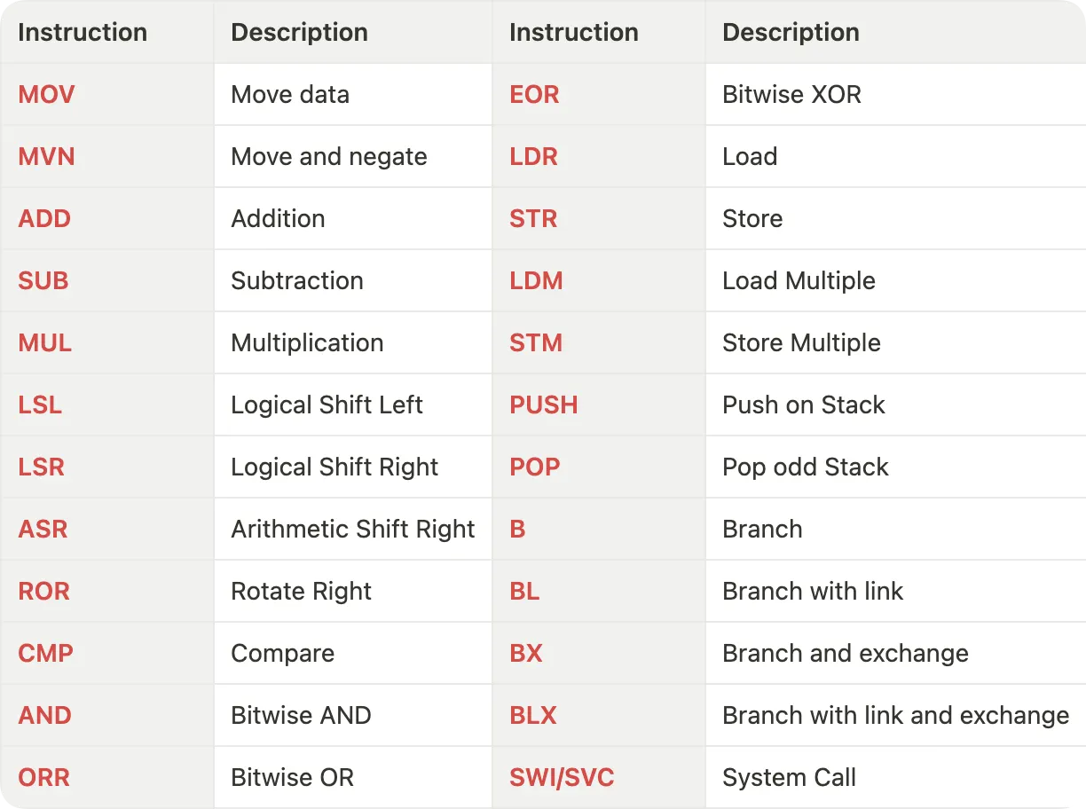
ARM OPCODES
As discussed before ARM follows RISC architecture thus only two operations can be performed on the memory i.e. LOAD and STORE. Let’s look at all the other most common instructions provided in the AAArch64 architecture.
MOV / MVN — Move
MOV r8, #10
MVN r9, r8
                      ; > [ mov / mvn ]  - instruction
                      ; > [ r8 ]         - register | Operand1
                      ; > [ #10 ]        - value | Operand2
Source: ARM Instruction Set Reference Guide v1.0
LDR — Load
LDR     r8, [r10]        ; loads R8 from the address in R10.
LDRNE   r2, [r5,#960]!   ; (conditionally) loads R2 from a word
                         ; 960 bytes above the address in R5, and
                         ; increments R5 by 960
Source: ARM Instruction Set Reference Guide v1.0
STR — Store
STR     r2, [r9,#consta-struc]   ; consta-struc is an expression
                                 ; evaluating to a constant in
                                 ; the range 0-4095.
Source: ARM Instruction Set Reference Guide v1.0
ADD — Addition
ADD r8, r8, r9
                      ; > [ add ]       - instruction
                      ; > [ r8 ]        - register | Operand1
                      ; > [ r8 ]        - register | Operand2
                      ; > [ #10 ]       - register | Operand3

; This instruction stores the addition between operand2 and operand3
; and store it in operand1.
Source: ARM Instruction Set Reference Guide v1.0
SUB — Subtraction
SUB r8, r8, r9
                      ; > [ sub ]       - instruction
                      ; > [ r8 ]        - register | Operand1
                      ; > [ r8 ]        - register | Operand2
                      ; > [ #10 ]       - register | Operand3

; This instruction stores the subtraction between operand2 and operand3
; and store it in operand1.
Source: ARM Instruction Set Reference Guide v1.0
MUL — Multiplication
MUL r8, r8, r9
                      ; > [ mul ]       - instruction
                      ; > [ r8 ]        - register | Operand1
                      ; > [ r8 ]        - register | Operand2
                      ; > [ #10 ]       - register | Operand3

; This instruction stores the multiplication between operand2 and operand3
; and store it in operand1.
Source: ARM Instruction Set Reference Guide v1.0
Code to CPU Instruction
To understand how a high-level code is converted into CPU instructions and what happens inside a CPU we will take an example code and decode the operation one by one.
I am on a MacBook Pro with an M2 Pro chip based on ARM architecture and follows the AAArch64 ISA. This assembly code generated here will follow the ARM ISA and mnemonics. In case, you are on a Windows computer and Intel or AMD-based chipset, your ISA will be different.
Below is a simple code in C that adds two numbers and stores the result in a third variable.
#include<stdio.h>
int main(){
 int a = 5;
 int b = 10;
 int c = a + b;
}
You can get the assembly from the above C file using the following command.
gcc -c -S <filename>.cHere is the assembly code, let’s go through it line by line to understand how ARM processors perform certain operations.
.section __TEXT,__text,regular,pure_instructions
 .build_version macos, 14, 0 sdk_version 14, 2
 .globl _main                           ; -- Begin function main
 .p2align 2
_main:                                  ; @main
 .cfi_startproc
; %bb.0:
 sub sp, sp, #16               ; Moving the SP 16 bytes back
 .cfi_def_cfa_offset 16
 mov w8, #5                    ; Moving 5 in register w8
 str w8, [sp, #12]             ; Storing the value in w8 to 12 byte
                                ; ahead of the SP
 mov w8, #10                   ; Moving 10 in w8
 str w8, [sp, #8]              ; Storing the value in w8 to 8 byte
                                ; ahead of the SP
 ldr w8, [sp, #12]             ; Loading value at 12 byte ahead of SP in w8
 ldr w9, [sp, #8]              ; Loading value at 8 byte ahead of SP in w9
 add w8, w8, w9                ; Adding values in w8 and w9 and storing in w8
 str w8, [sp, #4]              ; Storing value in w8 to 4 byte ahead of SP
 mov w0, #0                    ; Moving 0 to w0
 add sp, sp, #16               ; Adding 16 to SP and storing in SP.
                                ; (SP moves back at original position)
 ret                           ; return
 .cfi_endproc
                                        ; -- End function
.subsections_via_symbols
To begin with, below is the section of the assembly code that we need to look at and analyse. The lines before these are just function declarations and some configurations. Discussing them is out of the scope of this article. However curious readers can look for details in the provided references.
1.  mov  w8, #5                   ; Moving 5 in register w8
2.  str  w8, [sp, #12]            ; Storing the value in w8 to 12 byte
                                  ; ahead of the SP
3.  mov  w8, #10                  ; Moving 10 in w8
4.  str  w8, [sp, #8]             ; Storing the value in w8 to 8 byte
                                  ; ahead of the SP
5.  ldr  w8, [sp, #12]            ; Loading value at 12 byte ahead of SP in w8
6.  ldr  w9, [sp, #8]             ; Loading value at 8 byte ahead of SP in w9
7.  add  w8, w8, w9               ; Adding values in w8 and w9 and storing in w8
8.  str  w8, [sp, #4]             ; Storing value in w8 to 4 byte ahead of SP
9.  mov  w0, #0                   ; Moving 0 to w0
10. add  sp, sp, #16              ; Adding 16 to SP and storing in SP.
                                  ; (SP moves back at original position)
Analysis of the code
On close inspection, you can figure out the mnemonics in the instructions and the register names in the user. We are referring to the 32-bit registers (W) in AAArch64 architecture.
- In the first step, we are moving the value of 5 in the first register i.e. W8. If you look carefully, it’s this line from the C code:
int a = 5; - In the second step, we are storing the value at the location 12 bytes above the location in the Stack Pointer (SP stands for stack pointer).
- In the third line, we are moving value 10 in the W8 register. This is similar to the line
int b = 10;in the C program. - In the fourth step, we are storing the value at the location 8 bytes above the location in the SP.
- In the fifth line, we are loading the value at 12 bytes ahead of SP in register W8.
- In the sixth line, we are loading the value at 8 bytes ahead of SP in register W9.
- In the seventh line, we are adding the values in W8 and W9 and moving the value back to W8. This is this line in the C code:
int c = a + b; - In the eighth line, we are storing the value in W8 at 4 bytes above the SP location.
- In the ninth line, we are moving 0 inside W0. In GCC, the first parameter register (W0 in ARM64) is used for storing the exit code of the program. Thus moving 0 to W0 indicates the successful execution of the program.
- In the last line, we are moving the SP 16 bytes ahead by adding 16 to the SP.
With this, I would like to conclude this article.
Conclusion
This introduction has provided a basic understanding of the ARM assembly language and some fundamental instructions. We’ve seen how ARM processors operate on data using load-store architecture and how a simple C program translates into assembly instructions.
As you continue your exploration of ARM assembly, you can delve deeper into more complex instructions, branching statements, and assembly specific to different ARM cores. I have referenced different resources I came across while researching for this article. Feel free to explore them.
References
- ARM System Developers Guide: Designing and Optimizing System Software
- The ARM University Program, ARM Architecture Fundamentals
- ARM Instruction Set Reference Guide
Thank you for giving your valuable time.
I hope this article gave you some insight into how your valuable and beautiful code provides instruction to the hardware. This is my first article on an upcoming series of Computer Architecture and Organisation, and Low-Level Programming.
Please write your feedback on the delivery and the composition. Also, do let me know if I missed or misunderstood anything. One of my primary goals is to gain more knowledge and insight from valuable and enlightened audiences on the platform.